Die casting is a manufacturing process that can produce geometrically complex metal parts through the use of reusable molds, called dies. The die casting process involves the use of a furnace, metal, die casting machine, and die. The metal, typically a non-ferrous alloy such as aluminum or zinc, is melted in the furnace and then injected into the dies in the die casting machine. There are two main types of die casting machines - hot chamber machines (used for alloys with low melting temperatures, such as zinc) and cold chamber machines (used for alloys with high melting temperatures, such as aluminum). The differences between these machines will be detailed in the sections on equipment and tooling. However, in both machines, after the molten metal is injected into the dies, it rapidly cools and solidifies into the final part, called the casting. The steps in this process are described in greater detail in the next section.
 |
| Die casting hot chamber machine overview |
 |
| Die casting cold chamber machine overview |
The castings that are created in this process can vary greatly in size and weight, ranging from a couple ounces to 100 pounds. One common application of die cast parts are housings - thin-walled enclosures, often requiring many ribs and bosses on the interior. Metal housings for a variety of appliances and equipment are often die cast. Several automobile components are also manufactured using die casting, including pistons, cylinder heads, and engine blocks. Other common die cast parts include propellers, gears, bushings, pumps, and valves.
The process cycle for die casting consists of five main stages, which are explained below. The total cycle time is very short, typically between 2 seconds and 1 minute.
Clamping
- The first step is the preparation and clamping of the two halves of the die. Each die half is first cleaned from the previous injection and then lubricated to facilitate the ejection of the next part. The lubrication time increases with part size, as well as the number of cavities and side-cores. Also, lubrication may not be required after each cycle, but after 2 or 3 cycles, depending upon the material. After lubrication, the two die halves, which are attached inside the die casting machine, are closed and securely clamped together. Sufficient force must be applied to the die to keep it securely closed while the metal is injected. The time required to close and clamp the die is dependent upon the machine - larger machines (those with greaterclamping forces) will require more time. This time can be estimated from the dry cycle time of the machine.Injection
- The molten metal, which is maintained at a set temperature in the furnace, is next transferred into a chamber where it can be injected into the die. The method of transferring the molten metal is dependent upon the type of die casting machine, whether a hot chamber or cold chamber machine is being used. The difference in this equipment will be detailed in the next section. Once transferred, the molten metal is injected at high pressures into the die. Typical injection pressure ranges from 1,000 to 20,000 psi. This pressure holds the molten metal in the dies during solidification. The amount of metal that is injected into the die is referred to as the shot. The injection time is the time required for the molten metal to fill all of the channels and cavities in the die. This time is very short, typically less than 0.1 seconds, in order to prevent early solidification of any one part of the metal. The proper injection time can be determined by the thermodynamic properties of the material, as well as the wall thickness of the casting. A greater wall thickness will require a longer injection time. In the case where a cold chamber die casting machine is being used, the injection time must also include the time to manually ladle the molten metal into the shot chamber.Cooling
- The molten metal that is injected into the die will begin to cool and solidify once it enters the die cavity. When the entire cavity is filled and the molten metal solidifies, the final shape of the casting is formed. The die can not be opened until the cooling time has elapsed and the casting is solidified. The cooling time can be estimated from several thermodynamic properties of the metal, the maximum wall thickness of the casting, and the complexity of the die. A greater wall thickness will require a longer cooling time. The geometric complexity of the die also requires a longer cooling time because the additional resistance to the flow of heat.Ejection
- After the predetermined cooling time has passed, the die halves can be opened and an ejection mechanism can push the casting out of the die cavity. The time to open the die can be estimated from the dry cycle time of the machine and the ejection time is determined by the size of the casting's envelope and should include time for the casting to fall free of the die. The ejection mechanism must apply some force to eject the part because during cooling the part shrinks and adheres to the die. Once the casting is ejected, the die can be clamped shut for the next injection.Trimming
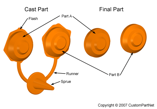
- During cooling, the material in the channels of the die will solidify attached to the casting. This excess material, along with any flash that has occurred, must be trimmed from the casting either manually via cutting or sawing, or using a trimming press. The time required to trim the excess material can be estimated from the size of the casting's envelope. The scrap material that results from this trimming is either discarded or can be reused in the die casting process. Recycled material may need to be reconditioned to the proper chemical composition before it can be combined with non-recycled metal and reused in the die casting process
Hot chamber die casting machine
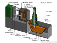
- Hot chamber machines are used for alloys with low melting temperatures, such as zinc, tin, and lead. The temperatures required to melt other alloys would damage the pump, which is in direct contact with the molten metal. The metal is contained in an open holding pot which is placed into a furnace, where it is melted to the necessary temperature. The molten metal then flows into a shot chamber through an inlet and a plunger, powered by hydraulic pressure, forces the molten metal through a gooseneck channel and into the die. Typical injection pressures for a hot chamber die casting machine are between 1000 and 5000 psi. After the molten metal has been injected into the die cavity, the plunger remains down, holding the pressure while the casting solidifies. After solidification, the hydraulic system retracts the plunger and the part can be ejected by the clamping unit. Prior to the injection of the molten metal, this unit closes and clamps the two halves of the die. When the die is attached to the die casting machine, each half is fixed to a large plate, called a platen. The front half of the die, called the cover die, is mounted to a stationary platen and aligns with the gooseneck channel. The rear half of the die, called the ejector die, is mounted to a movable platen, which slides along the tie bars. The hydraulically powered clamping unit actuates clamping bars that push this platen towards the cover die and exert enough pressure to keep it closed while the molten metal is injected. Following the solidification of the metal inside the die cavity, the clamping unit releases the die halves and simultaneously causes the ejection system to push the casting out of the open cavity. The die can then be closed for the next injection.
Hot chamber die casting machine - Opened
 Hot chamber die casting machine - Closed
 Cold chamber die casting machine - Opened 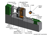
Cold chamber die casting machine - Closed
|

 bby metal casters because a lot of cost cutting can be done. In addition, one can be sure of getting dimensionally accurate castings with fine surface finish. But, this process is not economical than green sand casting process.